
ILX Connection user manual
ILX Connection v1.0.0 · AISC 360-22 · AISC Steel Construction Manual, 16th Ed.
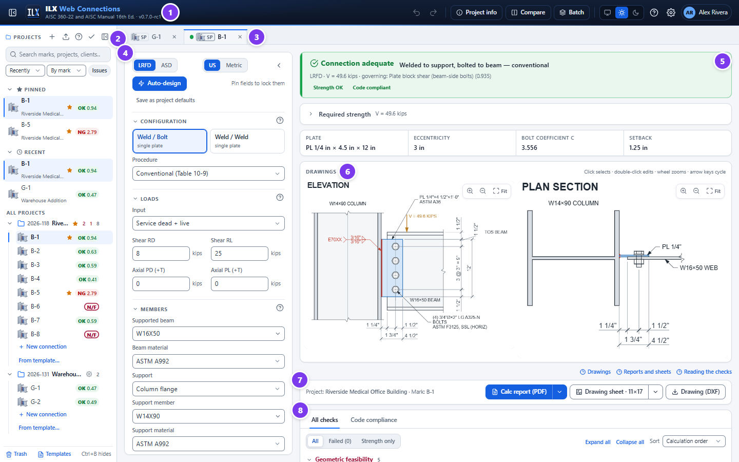
ILX Connection designs and details steel connections in a web browser. You enter the members, loads and connection geometry. ILX then checks every applicable limit state and detailing rule, draws the connection, and produces a calculation report and a title-blocked drawing sheet.
This release covers the connection types and component calculators below, each with its own editor, checks, drawings, report and sheet:
| Group | Type | Page |
|---|---|---|
| Simple shear | Single plate (shear tab, extended shear tab, all-welded plate; HSS through plate and round HSS) | Designing a single-plate connection |
| Simple shear | Single angle (bolted to the support; bolted or welded to the beam) | Designing a single-angle connection |
| Simple shear | Double angle (all-bolted, bolted / welded, all-welded) | Designing a double-angle connection |
| Simple shear | Shear end plate | Designing a shear end-plate connection |
| Simple shear | Seated (unstiffened bolted or welded, stiffened) | Designing a seated connection |
| Simple shear | Shear tee | Designing a shear tee connection |
| Simple shear | Skewed double bent plate (beam to girder web) | Designing a skewed double bent-plate connection |
| Moment | FR moment (directly welded flanges, bolted or welded flange plates; column stiffeners and doublers) | Designing an FR moment connection |
| Moment | End-plate moment (the 15 flush and extended configurations of AISC Design Guide 39; column continuity plates and doublers) | Designing an end-plate moment connection |
| Moment | Double-tee moment (AISC 358-22 Chapter 13, SMF and IMF; T-stubs, stiffness, column flange, continuity plates, panel zone) | Designing a double-tee moment connection |
| Splices | Beam shear splice; compression splice (column or chord) | Designing a splice |
| Truss & bracing | Truss support joint and panel point | Designing a truss connection |
| Truss & bracing | Tension member end connection | Designing a tension member end connection |
| Truss & bracing | Vertical bracing gusset (Uniform Force Method) | Designing a vertical bracing gusset (UFM) |
| Truss & bracing | Chevron bracing gusset | Designing a chevron bracing gusset |
| Truss & bracing | Horizontal bracing wrap-around gusset (cut out around the column; Manual Fig. 13-10) | Designing a horizontal bracing wrap-around gusset |
| Members | Built-up member connectors | Designing built-up member connectors |
| Members | Beam web opening | Designing a beam web opening |
| Hangers & bearing | Hanger; beam bearing plate; HSS strut end plate | Hangers, bearing plates and HSS strut end plates |
| Hangers & bearing | Column bearing on a beam | Designing a column bearing on a beam |
| Hangers & bearing | Crane-rail connection (rail fastening and rail splices, Manual Part 15) | Designing a crane-rail connection |
| Column bases | Column base plate (axial, moment, shear; anchor rods to ACI 318-19 Chapter 17) | Designing a column base plate |
| Column bases | Embedded column base (column set into the foundation, DG1 Chapter 5) | Designing an embedded column base |
| Column bases | Braced-frame base (brace gusset on the column and the plate; DG29 §4.3) | Designing a braced-frame column base |
| Components & calculators | Bracket plate, bolt group, weld group, bolted joint, welded joint | Components and calculators |
What ILX does #
- Connection types. The types above, chosen in the wizard's Connection type step (see Choosing the connection type).
- Supports. Column flange, column web, girder web (with top-of-steel offset) and HSS column wall, as each type allows. Base plates sit on a concrete pier or footing.
- Loads. LRFD or ASD in US or metric units, from any of these:
- service dead and live loads;
- service components combined by ASCE 7-22;
- required strength entered directly;
- a table of factored load cases.
Shear can be combined with axial tension or compression where the type supports it. FR and end-plate moment connections and base plates take moments as well.
- Bolts. Bearing-type and slip-critical joints, every ASTM F3125 grade (plus F3043, A307 and threaded rod), every hole type, and fillers.
- Welds. Fillet welds by the instantaneous-center method, one-sided or both-sided support welds (single plate), and CJP groove welds (FR moment, base plates).
- Copes. Top, bottom and double copes, with the reentrant-corner radius.
- Checks. Each check shows its code clause, the required and available values, the ratio and a fix hint.
- Feasibility. A geometric feasibility gate marks any connection that cannot be built as NOT FEASIBLE.
- Design tools. Auto-design for every type, batch design of a schedule of marks, and side-by-side comparison.
- Outputs:
- interactive on-screen drawings;
- a configurable PDF calculation report;
- a drawing sheet with your title block, as PDF and DXF.
- Project files. Projects and connections are stored on the server under your account, with search, pins, templates, version history, trash, and import and export.
What ILX does not do #
ILX follows the AISC Specification, Manual, design guides and seismic standards as written. Where a provision leaves a value or a choice to the engineer of record, ILX asks for it (with a stated default) and reports it; it does not assume it. The items below are outside what ILX designs today.
- Member design. The beam, column, brace and support are checked only for the local limit states of the connection (web shear, coped sections, column flange and web local limit states, panel zone, out-of-plane strength). Member design, including runway girders, is not included.
- Shop drawings. The drawings are schematic connection details, not fabrication drawings.
- Seismic. AISC 358-22 RBS, WUF-W, BFP, BUEEP/BSEEP and double-tee connections and the AISC 341-22 SCBF, OCBF, EBF and BRBF connection rules are designed. Proprietary and cast 358 connections (Chapters 9 to 12, 14 and 15), built-up, boxed and cruciform columns, plug-welded doublers and knife-plate brace details are not.
- Skewed and sloped details. Skewed single plates and end plates, single and double bent plates, and sloped beams on single plates and angles are designed. Canted beams, combined skew and slope, skewed or sloped seats, all-bolted or wrapped single bent plates, and a slope on shear tees, end plates and seats are not; sloped elevations are drawn square.
- HSS supports. Angles may be through-bolted or blind-bolted to a rectangular HSS wall; round HSS walls and HSS walls under axial tension from bolted angles (J3.13) are not covered.
- Fatigue. AISC 360 Appendix 3 is designed for the details of the wired types (see each type's page); bracing gussets, splices, PR moment and several calculators are not wired yet, and distortion-induced fatigue is not checked.
- Chevron gussets. The Concentrated Stress Method follows the Manual's description only (Sabelli and Saxey 2021, EJ 58(1), is not on file); the Uniform Stress Method is the default.
- Crane rails. Web yielding and crippling of the runway girder under the wheel, the rail section, and clip, clamp and hook components are not checked; the rail fastening bolts, Part 15 / DG7 / CMAA detailing and the crane forces are.
Design basis #
| Topic | Basis |
|---|---|
| Specification | ANSI/AISC 360-22, Specification for Structural Steel Buildings |
| Design aids | AISC Steel Construction Manual, 16th Ed.: Part 7 (bolts, instantaneous center), Part 8 (welds), Part 9 (connecting elements, coped beams), Part 10 (simple shear connections), Part 11 (FR and PR moment connections), Part 12 (simple connections for combined forces), Part 14 (column base plates) |
| Base plates | AISC Design Guide 1, 3rd Ed. (base plate and anchor rod design); ACI 318-19 Chapter 17 (anchoring to concrete) |
| Worked examples | AISC Design Examples v16.0 (Chapter II.A simple shear, II.B moment, J and K examples), which set the default bolt-group method; DG1 examples for base plates |
| Load combinations | 1.2D + 1.6L and 1.4D (LRFD), or D + L (ASD); or the ASCE/SEI 7-22 strength (2.3) and allowable stress (2.4) combinations |
| Shapes | AISC Shapes Database v16.0 (2,299 shapes) |
| Units | US customary by default, SI selectable. Calculations run internally in US units. |
| Drafting | AISC detailing practice, NCS/UDS layers and title block, AWS A2.4 weld symbols |
The verification of the calculations against published examples is summarised in Verification.
Engineer-of-record responsibility #
ILX is a design aid. It does not replace engineering judgement, and it does not know your project's load path, construction sequence or contract requirements. The engineer of record remains responsible for:
- the design, and for checking that the inputs (loads, members, materials and geometry) are correct;
- deciding whether the limit states and methods ILX applies are appropriate for the project;
- reviewing every report and drawing before it is issued, and sealing it where required.
Every report ends with a disclaimer to this effect, which you can edit in the report settings.
How this manual is organised #
| Page | Read it when you want to… |
|---|---|
| Getting started | Sign in, learn the layout and design your first connection |
| Projects and files | Organise, find, copy, version, import, export or back up your work |
| Designing a single-plate connection | Choose a connection type and a configuration and enter members, loads, bolts, plate, copes and welds; use auto-design, compare and batch |
| Single angle, double angle, shear end plate, seated, shear tee | Design the other simple shear connection types |
| Skewed double bent plate | Design a skewed beam-to-girder connection with bent plates |
| Designing an FR moment connection | Design a fully restrained moment connection and its column stiffening |
| Designing a double-tee moment connection | Design the AISC 358 double-tee connection of a special or intermediate moment frame |
| Designing a splice | Design a beam shear splice or a column / chord compression splice |
| Designing a truss connection | Design a truss support joint or a panel point |
| Designing a horizontal bracing wrap-around gusset | Design a horizontal brace gusset cut out around a column |
| Hangers, bearing plates and HSS strut end plates | Design a hanger, a beam bearing plate or an HSS strut end plate |
| Designing a crane-rail connection | Fasten a crane rail to a runway girder and detail the rail splices |
| Designing a column base plate | Design a column base plate and its anchor rods |
| Designing a braced-frame column base | Design the base plate and gusset at a braced frame |
| Components and calculators | Check a bracket plate, a bolt or weld group, or a bolted or welded joint |
| Checks and compliance | Read the results and fix failing or infeasible connections |
| Drawings | Use the on-screen drawings, drawing sheets and DXF files |
| Reports | Produce and configure calculation reports and project packages |
| Settings | Set up your title block and report defaults, project overrides, users |
| Verification | See how ILX was verified against the AISC Design Examples |
| FAQ and troubleshooting | Solve common problems |
| Glossary | Look up a term or abbreviation |