
Designing a shear tee connection
A shear tee connection is a simple shear connection made of one tee: a rolled WT, or a tee built up from two plates. The tee flange is bolted or welded to the support, and the tee stem is bolted or welded to the beam web. ILX designs it to AISC Manual 16th Ed. Part 10 and AISC 360-22, as in Design Examples II.A-30, II.A-31, K.1 and K.2.
When to use it #
- Use a shear tee when you want a one-sided connection that is bolted to the support (the single plate cannot be), or when a single plate or single angle does not have the capacity.
- Use a tee on an HSS column when the flange should be welded to the HSS face (narrow tee, K.2) or across the HSS corners (wide tee, K.1).
- Use a single plate when the support side is shop-welded and a plate is enough.
- Use a double angle for a symmetric connection with angles on both sides of the beam web.
- Use a single angle for light reactions with an angle bolted to the support.
The two parts of the tee have their own names in the app. The flange lies against the support. The stem lies against the beam web. The stem is offset from the support centerline by (tw + tsw)/2, the half thicknesses of the beam web and the stem.
Creating one in the wizard #
- In the wizard's Connection type step, select the Tee card in the Simple shear group.
- Under Joint type, select Beam to column flange, Beam to column web, Beam to girder web or Beam to HSS column. Selecting the HSS column changes the flange to welded.
- Under Configuration, select a card. The first word is the flange (support side), the second the stem (beam side):
| Card | Sets | Basis |
|---|---|---|
| All-bolted tee | Flange bolted to the support, stem bolted to the beam | Example II.A-30 |
| Welded / bolted tee | Flange welded to the support, stem bolted to the beam | Example II.A-31 (and K.1, K.2 on an HSS) |
| Bolted / welded tee | Flange bolted to the support, stem welded to the beam | Manual Part 10 |
| All-welded tee | Flange welded to the support, stem welded to the beam | Manual Part 10 |
On an HSS column, All-bolted tee and Bolted / welded tee are greyed out. Their tooltip reads A tee flange is welded to an HSS wall.
- Members. Enter the Connection mark (new marks are numbered TE-1, TE-2 and so on), the Supported beam, the Column, Girder or HSS column, and the Tee (WT). A built-up tee is chosen later, in the editor.
- Loads. Choose Service D + L (Dead RD, Live RL) or Required strength (Shear Ru or Ra, and Axial with + for tension). The other load modes are in the editor.
- Tick Auto-design the connection (tee, bolts) for these loads to size the connection as it is created. The wizard keeps the beam, the support, the joint type and the configuration, and uses the lightest (steel weight) objective.
- Select Create.
Inputs in the editor #
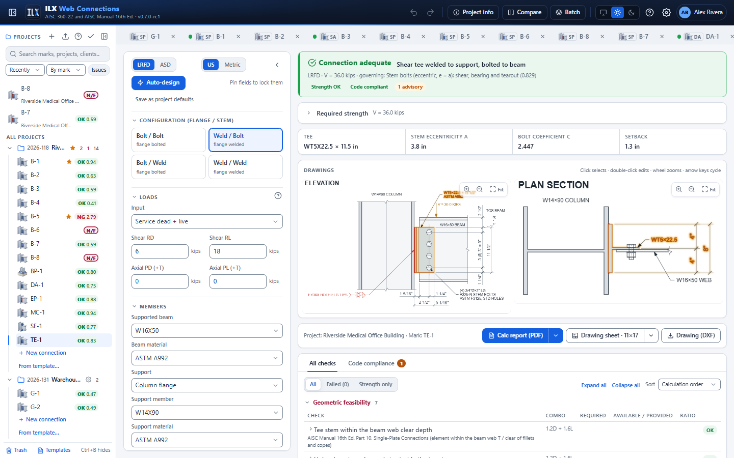
The input panel has these sections, in this order. Sections and fields that do not apply to the configuration are hidden: the Bolts section for the all-welded tee, the stem bolt fields for a welded stem, and the flange bolt fields for a welded flange. The key-geometry strip under the status shows Tee (for example WT5X22.5 × 11-1/2 in), Stem eccentricity a, Bolt coefficient C and Setback.
Configuration (flange / stem) #
| Field | Options and notes |
|---|---|
| Configuration buttons | Bolt / Bolt (all-bolted tee, II.A-30), Weld / Bolt (II.A-31), Bolt / Weld, Weld / Weld. The first word is the flange to the support, the second the stem to the beam. Each button says flange bolted or flange welded. |
Choosing a bolted flange while the support is an HSS wall changes Support to Column flange. Choose a W-shape Support member after the change.
Loads and axial force #
The Loads section is the shared one; see Loads and load combinations. All four input modes are supported: Service dead + live, Service components → ASCE 7 combinations, Required strength (Ru, Pu) and Factored load cases (table). Axial tension and compression are both supported. With ASCE 7 combinations or load cases, each combination is checked and the envelope governs.
Members and support #
| Field | Options and notes |
|---|---|
| Supported beam, Beam material | AISC W shape; ASTM A992, A572 Gr. 50 and so on |
| Support | Column flange, Column web, Girder web, or HSS column wall (welded flange only). With a bolted flange the panel says HSS walls need a welded tee flange. |
| Support member, Support material | A W shape, or an HSS shape for the HSS wall with an HSS material (A500, A1085, A53 Gr. B). When you change Support, pick a matching member. |
| Connected HSS face | HSS wall: B (wide face) or H (narrow face) |
| Girder TOS − beam TOS (+ = beam lower) | Girder web only |
| Connections on both sides of the web | Column web or girder web. ILX then uses half the web thickness for this connection (bearing on the support, Manual Eq. 9-6 base metal, support shear rupture). |
| Connection near the column end, Column end to the connection force | Column web or column flange. Cleared (default): the connection is not near the column end. Ticked: enter the distance from the column end to the force. Column web: when it is less than √(8wab/(a + b)), ILX halves the Eq. 9-45 yield-line strength (Manual p. 9-18). Column flange with an axial force: web local yielding uses Eq. J10-3 when the distance is ≤ d, and web crippling Eqs. J10-5a/b when it is < d/2 (AISC 360-22 J10.2, J10.3). The report shows the limit, the distance and which equation was used. |
The tee #
| Field | Options and notes |
|---|---|
| Tee | Rolled WT or Built-up (plates) |
| WT shape | Rolled WT. The line under it gives d, bf, tf, tsw and the stem offset from the support centerline. |
| Overall depth d, Flange width bf, Flange thickness tf, Stem thickness tsw | Built-up tee only |
| Flange-to-stem fillet | Built-up tee only: the shop fillet on both faces of the stem |
| Tee material | A992, A36, A572 Gr. 50 and so on |
| Stripped flange width (0 = full) | Rolled WT only. A narrower flange for a narrow tee on an HSS flat (Example K.2). |
| Top of beam to top of tee | Where the tee sits on the beam web; it must clear the flange, fillet and any cope |
| Tee length, l | All-welded tee only. With bolts, the length follows from n, s and Lev. |
For a WT, k1 is taken from the parent W shape (WT5X22.5 from W10X45). For a built-up tee, k1 = tsw/2 + the flange-to-stem fillet.
Beam copes #
Tick Top cope, Bottom cope or both, and enter Top cope length c, Top cope depth dc (and the bottom equivalents) and the Reentrant corner radius. The cope checks are those of the single plate; see Beam copes.
Bolts and holes #
One bolt grade and diameter is used for the stem and the flange. The bolt rows are shared: the flange has two bolt lines with the same n and s as the stem.
| Field | Options and notes |
|---|---|
| Bolt grade, Bolt diameter, Threads | As for the single plate. Threads: Included (N) or Excluded (X). |
| Joint | Bearing (snug-tight), Bearing, pretensioned or Slip-critical; Surface Class A (μ = 0.30) or Class B (μ = 0.50) |
| Rows, n and Spacing, s | At least 2 rows whenever there are bolts |
| Lev, tee (top & bottom) | Vertical edge distance at the top and bottom bolts |
| Bolt group strength | Σ per-bolt strengths (Design Examples; default), n (or C) × weakest bolt (conservative) or Shear + Σ bearing/tearout (split) |
| Hole deformation at service is a design consideration (2.4 / 1.2) | Ticked: bearing 2.4 d t Fu and tearout 1.2 lc t Fu. Cleared: 3.0 and 1.5 (J3.11). |
Stem to beam #
The section title reads Stem to beam (bolted) or Stem to beam (welded).
| Field | Shows | Options and notes |
|---|---|---|
| Stem bolt columns, Column gage | Bolted stem | 1 to 3 columns; the gage shows with 2 or more |
| Stem holes, Beam web holes | Bolted stem | STD, OVS, SSL or LSL, horizontal or vertical |
| Leh, stem toe | Bolted stem | Last stem bolt column to the stem toe. a = tee depth − Leh, stem. |
| Leh, beam web | Bolted stem | First stem bolt column to the beam end |
| Support face to beam end (setback) | Welded stem | The beam end position |
| Fillet, stem to beam web, Weld shape | Welded stem | C-shape, Vertical or Top & bottom |
| Cb, stem lateral-torsional buckling | Always | Default 1.00, as in Example K.1 |
| K (stem in compression) | Net axial compression | Effective length factor for the stem in compression |
Flange to support #
The section title reads Flange to support (bolted) or Flange to support (welded).
| Field | Shows | Options and notes |
|---|---|---|
| Flange bolt gage g (centred on the support) | Bolted flange | The two bolt lines are centred on the support, not on the stem |
| Flange holes, Support holes | Bolted flange | Hole types as above |
| Fillet at each flange tip | Welded flange | One fillet along each flange tip. On a wide tee on an HSS, ILX uses flare-bevel groove welds at the HSS corners instead. |
| Flange weld eccentricity | Welded flange | Manual Table 10-2 (e = max(4 in., a)) (default, as in II.A-31), e = a, or None (flexible support, K.1/K.2) |
| Electrode | Always | E70XX or E80XX |
Service conditions and additional checks #
Hot-dip galvanized, Unpainted weathering steel, Cyclic loading (fatigue, AISC 360 Appendix 3), Structural integrity tension (AISC 360 B3.9) and End rotation / flange binding (with Required rotation and the presets 0.03 and 0.025 (341)) work as for the single plate; see Service conditions and additional checks. Weathering steel also lowers the flange bolt spacing limit to 14t ≤ 7 in.
Fatigue (Appendix 3). With Cyclic loading ticked the connection is designed for fatigue as for the single plate; see Fatigue (Appendix 3). The details: the tee stem, the tee flange and the beam web at the bolt holes (Table A-3.1 Section 2, or Case 1.5 for snug-tight joints), the stem-to-web fillets (elastic weld group, Case 8.2, F), the flange-tip welds to the support (two lines with the eccentricity of the strength check, Case 8.2, F) and the beam at a cope corner (Case 1.3).
Checks it runs #
The load path follows Manual Part 10: the flange bolts or welds carry the shear Rr; the stem bolts carry Rr at the eccentricity a, from the support face to the stem bolt group centroid. The stem and the beam are checked as a single plate welded to the tee flange, with the full eccentricity a. For reading the results, see Checks and compliance.
Rotational ductility (AISC Manual 16th Ed. Part 9, rotational ductility (Eqs. 9-51, 9-52, 9-53; Fig. 9-6))
- Bolted flange: d ≥ dmin, Eq. 9-52, with b from the stem centerline to the nearer bolt line minus k1, and p from Fig. 9-4.
- Welded flange: w ≥ wmin, Eq. 9-51, capped at (5/8) tsw. On a wide tee welded to an HSS, b uses B in place of bf (K.1).
- Bolted stem: tsw or tw ≤ d/2 + 1/16 in., Eq. 9-53. Eq. 9-53 is an alternate: when either rule is met, the other is shown as a recommendation.
- The extended single-plate tmax rule is advisory with one stem bolt column and required with two or more.
Stem bolts and stem
- Stem bolts (eccentric, e = a): shear, bearing and tearout by the instantaneous-center method (Manual Part 7), and slip resistance (J3.9).
- Tee stem shear yielding, shear rupture and block shear (J4.2, J4.3); tension, compression and axial block shear with axial load (J4.1, J4.4).
- Tee stem flexural yielding and lateral-torsional buckling as a rectangular bar, with Lb from the support face to the first stem bolt line (AISC 360-22 F11; Design Examples II.A-30, K.1).
- Tee stem flexural rupture, Mn = Fu Znet (J4.5; Manual Eq. 9-8).
- With axial load: stem axial, flexure and shear interaction, yielding and rupture (Manual Part 12, Eqs. 12-2 and 12-3).
- Welded stem: the stem-to-beam weld group, size limits, and the beam web base metal.
Tee flange and flange bolts
- Tee flange shear yielding on two planes beside the stem (J4.2(a)); shear rupture through the bolt lines (J4.2(b)); block shear of both flange halves (J4.3).
- Flange-to-support bolts: shear, bearing and tearout, concentric (J3.7, Table J3.2; J3.11; Manual Part 10). Slip resistance, with ksc under tension (J3.9).
- With axial tension: flange bolts in tension with shear and prying, each bolt line with its statical share (J3.7, J3.8, Manual Part 9 prying action); column flange prying.
Flange welds and support
- Flange-to-support welds by the instantaneous-center method (J2.4, Table J2.5; Manual Part 8), with the chosen eccentricity.
- Minimum fillet (J2.2b, Table J2.4), maximum tf − 1/16 in. (J2.2b(b)), length ≥ 4w (J2.2b(c),(d)). Flare-bevel welds: minimum effective throat (J2.1, Tables J2.2 and J2.3).
- Support thickness develops the welds, tmin = 3.09 D/Fu, doubled with connections on both sides (Manual Part 9). The tee flange thickness check is a recommendation.
- Support shear rupture along the two weld lines (J4.2(b)). With tension: tee flange bending between the stem and the tip welds.
- Support under axial load: column web yield line (Manual Eq. 9-45; halved near the column end, noncritical when the load spans more than 85 % of the web width) and punching; girder web (approximate); column web local yielding and crippling (J10.2, J10.3); column flange bending under the tip welds (approximate, J10.1); HSS wall plastification or sidewall yielding, and round HSS Eq. K2-2a.
Beam: web shear, coped section, block shear, beam tension (D2, D3), cope flexure (Dowswell), framing geometry (girder flange, column-web fit) and end rotation, as for the single plate.
Structural integrity (B3.9(b)): the stem-side group plus flange bolts in tension with prying, or flange welds in transverse tension and tee flange bending.
Geometry and feasibility. The design is NOT FEASIBLE when the beam end does not clear the tee flange, the stem holes fall in the tee fillet (x − dh/2 ≥ kdes), the flange bolts fall in the stem fillet or outside the flange, the tee flange and bolts or welds do not fit on the support, or a tee on an HSS flat is neither narrow nor wide (K.2). Further detailing checks: edge distances on the flange (J3.4, J3.5; a flange-tip edge between d and Le,min is a recommendation under Table J3.4 footnote [a], as in II.A-30), maximum edge and spacing (J3.6), slip-critical requirements for oversized and slotted holes, washers, bolt grip, tightening clearances (Manual Tables 7-15 and 7-16), and a setback of at least 1/2 in. beyond the flange.
Drawings, report and sheet #
The editor and the sheet show two views:
- Elevation: the tee flange edge-on against the support with its fillet line, the stem on the beam web, the flange bolts in side view (head on the support, nut on the tee flange) and the stem bolts in end view.
- Plan section: the full T, with the flange across the support face, the flange bolts through the flange and the support, and the stem bolts through the stem and the beam web. On a wide tee on an HSS, the rounded HSS corners with the flare-bevel welds.
The tee callout gives the WT and length (and the stripped flange width), or the built-up flange and stem plates. Each bolt callout gives the bolt length of its group (STEM BOLTS, FLANGE BOLTS). The weld symbols read BOTH FLG TIPS, BOTH HSS CORNERS (flare-bevel), the stem weld shape (3 SIDES, END, TOP & BOT, field weld) and FLG TO STEM for a built-up tee.
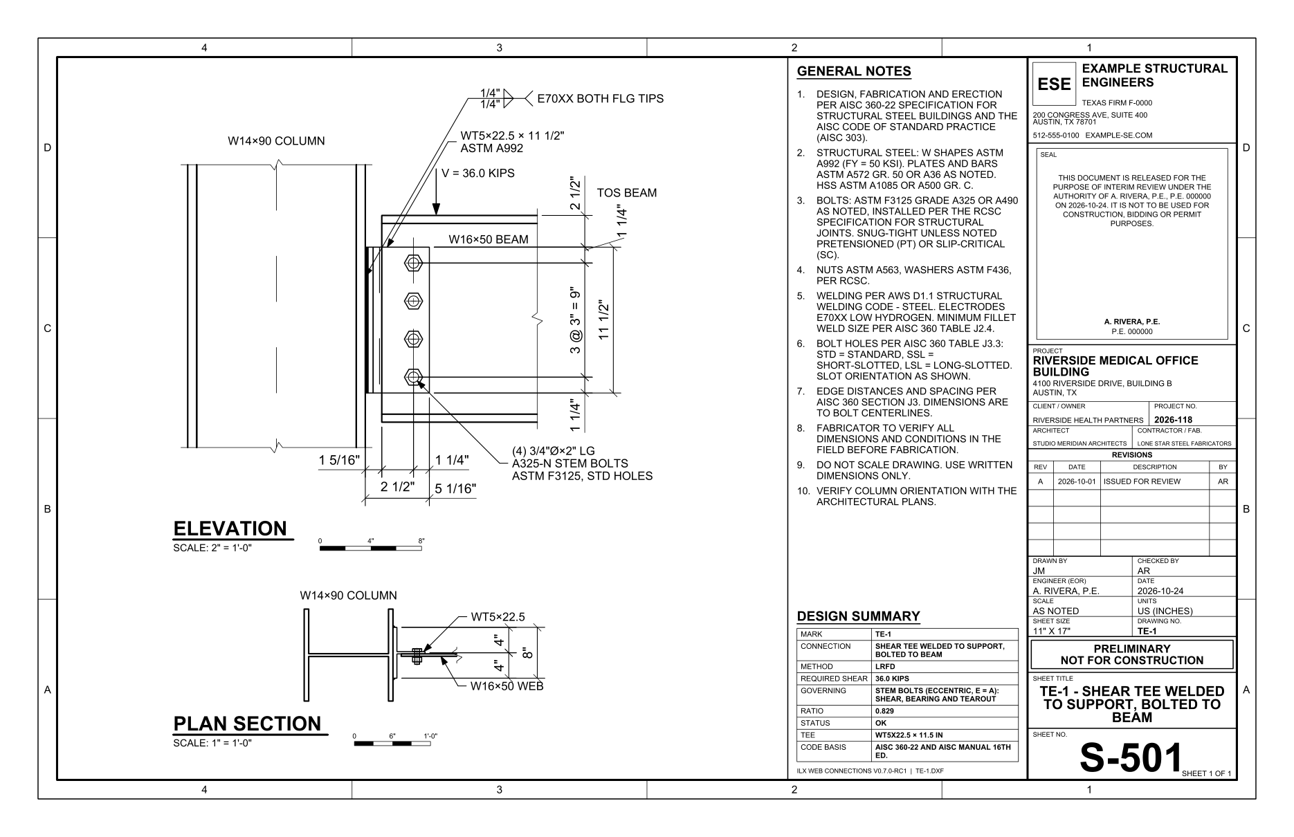
The report is titled Shear Tee Connection, with the configuration (for example All-bolted shear tee). Its input summary lists the tee and its dimensions (d, bf, tf, tsw, k1), the stem bolts with a, the flange bolts or welds with the weld eccentricity, and the setback. See Drawings and Reports.
Auto-design, compare and batch #
Auto-design searches the bolt rows n (2 to 8), the bolt diameter (3/4, 7/8 and 1 in.) and the rolled tee, from WT4X9 to WT9X43, lightest first. Pinned fields are kept. In the editor, the button's tooltip reads Search bolt rows, bolt size and the WT; pinned fields are kept. The objectives are those of the shared dialog:
- Lightest (steel weight): the tee weight, plus the weld weight;
- Fewest bolts: stem bolts plus 2n flange bolts;
- Lowest cost (fabrication estimate): bolts, welds and steel.
Auto-design does not change the configuration, the support, the bolt grade, the weld sizes or the tee type. See Auto-design, compare and batch for the dialog.
Compare works for shear tees. Batch design reads the columns beam, support, RD and RL (plus any input field name). With Auto-design each mark, each mark is searched over the same rows, bolt sizes and tees.
Limitations and documented deviations #
Verification. The results match Design Examples II.A-30, II.A-31, K.1 and K.2 within 0.5 percent, in LRFD and ASD: stem bolts, stem shear yielding, rupture and block shear, flange bolts, stem flexure (yielding, rupture, and LTB in K.1), flange welds (Table 10-2 Welds B, 99.7 / 66.5 kips), flare-bevel and fillet welds on the HSS, dmin (0.481 in.), wmin, and the minimum support thickness. K.1 stem flexural yielding is 0.4 to 0.5 percent high because AISC rounds Z to 11.2 in.³ See How ILX was verified.
Methods that differ from the Design Examples
- Weld eccentricity. The default e = max(4 in., a) reproduces Manual Table 10-2 Welds B, which is for double angles; II.A-31 uses it for the tee. It is a user option.
- Stem lateral-torsional buckling is checked in every case, with Cb = 1.00 (K.1). II.A-30 and II.A-31 do not check it.
- Extended tmax is advisory with one stem bolt column (II.A-30 would fail it), and enforced with two or more.
- Flange-tip edge distance below Le,min is accepted down to one bolt diameter (an ILX choice).
Approximate checks, flagged in the results: girder-web out-of-plane strength, column-flange bending under the welded flange tips, HSS sidewall yielding for a wide tee (k = 1.5t), HSS face plastification with b1 = bf, and the HSS shelf of max(1/2 in., w + 1/4 in.) in the narrow-tee rule. The Design Examples assume flexible supports and check none of the support checks for shear alone.
Scope
- No Manual design table exists for shear tees; the tee is designed by calculation, as in the examples.
- One bolt grade and diameter for the stem and the flange; two flange bolt lines with the stem's rows. The flange bolts are concentric.
- A bolted flange is not allowed on an HSS wall.
- Not checked: flexural yielding of the tee flange under shear alone (the examples state it does not control), skewed or inclined tees, and the Astaneh and Nader test limits (bf/2tf ≥ 6.5, db/ts ≥ 2), which are not Manual requirements.