
How ILX was verified
Every ILX connection type and calculator is verified against complete published design examples, limit state by limit state, for LRFD and ASD. The full record for the single plate and single angle is the Verification Manual (docs/VERIFICATION_MANUAL.md, issue 0.4-B); the other types are summarised in its §6C and shown in full on the Verification page. This page summarises it.
Opening the Verification page #
- Select the gear in the header to open Settings.
- Select the Verification tab.
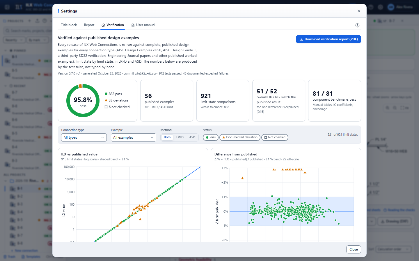
The page is generated from the verification tests at each release. It shows the version and date it was generated, and contains:
- Summary tiles: the pass ring (pass, deviations, not checked), the number of published examples and LRFD/ASD runs, the limit-state comparisons, how many overall OK/NG results match the published ones, and the component benchmarks that pass.
- Filters: Connection type, Example, Method (Both, LRFD or ASD) and Status.
- Charts: ILX against published values, and the difference from the published value against the tolerance band. Click a point to open its row.
- Examples: one card per example, with the source and pages. Expand a card for the limit-state table: published value, ILX value, Δ %, Δ against the tolerance and the status.
- Documented deviations, in plain language: what differs, why, and its effect, with a link to the affected examples.
- Component benchmarks: instantaneous-center coefficients, bearing and tearout, and slip resistance.
- Download verification report (PDF): the same content as a typeset PDF to attach to a submittal.
Method #
- Benchmark comparison. Each published example is entered into ILX field by field, using the drawn geometry. Every published quantity is compared with the value ILX computes: the check capacity, its demand, or a named calculation step. The numbers in the tables are generated by the test code, not typed.
- Component benchmarks.
- Instantaneous-center coefficients against Manual Tables 7-6, 7-7, 8-4, 8-8 and 8-10.
- Bearing and tearout against Tables 7-4 and 7-5.
- lc along the resultant against Design Example II.A-1B.
- Slip resistance against Design Example J.4A and J3.9.
- The rows of Manual Table 10-9.
- SI and US consistency. Every example is run again in SI units, and every check must match its US result.
- Robustness. Property-based fuzzing sends thousands of random and plausible inputs. None may produce a server error, and the strength ratios must be sensible.
Acceptance. Forces must agree within ±1 % or ±0.5 kip, whichever is larger. Moments and coefficients must agree within ±1 %, and interaction ratios within ±2 %. Published values are printed to three significant figures, so they carry up to 0.5 % rounding.
Single plate and single angle #
| Example | What it is | ILX result | Published |
|---|---|---|---|
| AISC II.A-17A | Conventional single plate to a column flange | OK | OK |
| AISC II.A-17B | Conventional single plate, axial + shear, to a column flange | OK | OK |
| AISC II.A-18 | Single plate to a girder web, top-coped beam | OK | OK |
| SDS2 II.A-18 | SDS2's published verification of II.A-18 (all 17 values) | OK | OK |
| AISC II.A-19A | Extended single plate to a column web | OK | OK |
| AISC II.A-19B | Extended single plate, axial + shear, to a column web | NG (column-web yield line) | NG (same reason) |
| AISC II.A-28A | All-bolted single angle to a girder web | OK | OK |
| AISC II.A-29 | Bolted/welded single angle (element checks only) | – | OK |
| Muir & Thornton (2011) | Conventional single plate | OK | OK |
| Muir & Hewitt (2009) | Extended single plate | NG | OK (2009 code edition, see below) |
| Dowswell (2018) | Single-coped beam | – | OK |
| AISC K.6 | Single plate to a rectangular HSS column | OK | OK |
| AISC K.7 | Through plate to a rectangular HSS column | OK | OK |
| AISC K.8 | Longitudinal plate on a round HSS, load perpendicular to the HSS axis | OK | OK |
Across the 14 examples, 404 limit-state values were compared in LRFD and ASD:
- 376 pass within tolerance. All 82 values from the HSS examples K.6, K.7 and K.8 pass.
- 24 are documented deviations.
- 4 are limit states ILX does not compute (coverage gaps).
All 24 component benchmarks pass, most within 0.5 %. In every AISC example it models, ILX reaches the published overall result for the published reason.
Every connection type #
The Verification page shows all of them; filter by Connection type to see one.
| Type | Examples | Limit states | Pass | Deviation | Not checked |
|---|---|---|---|---|---|
| Single plate | 12 | 352 | 336 | 16 | 0 |
| Single angle | 2 | 52 | 40 | 8 | 4 |
| Double angle | 11 | 137 | 135 | 2 | 0 |
| Shear end plate | 3 | 126 | 124 | 2 | 0 |
| Seated | 9 | 98 | 94 | 2 | 2 |
| Shear tee | 4 | 60 | 60 | 0 | 0 |
| Skewed bent plate | 1 | 34 | 32 | 2 | 0 |
| FR moment | 4 | 108 | 108 | 0 | 0 |
| Beam shear splice | 2 | 64 | 58 | 6 | 0 |
| Compression splice | 3 | 44 | 44 | 0 | 0 |
| Truss connection | 3 | 124 | 124 | 0 | 0 |
| Hanger | 1 | 60 | 60 | 0 | 0 |
| Beam bearing plate | 3 | 42 | 42 | 0 | 0 |
| HSS strut end plate | 1 | 28 | 28 | 0 | 0 |
| Base plate | 14 | 70 | 67 | 3 | 0 |
| Bracket plate | 2 | 90 | 86 | 4 | 0 |
| Bolt group | 3 | 26 | 26 | 0 | 0 |
| Weld group | 3 | 28 | 28 | 0 | 0 |
| Bolted joint | 5 | 66 | 66 | 0 | 0 |
| Welded joint | 4 | 54 | 54 | 0 | 0 |
| Total | 90 | 1,663 | 1,604 | 45 | 14 |
All 85 component and Manual-table benchmarks pass. Each deviation and coverage gap has its plain-language explanation on the Verification page.
Known deviations (single plate and single angle) #
These differences are method choices that AISC permits, or errors and edition differences in the sources. None changes an overall result.
| Topic | Difference | Why |
|---|---|---|
| Tearout (II.A-17B, II.A-19B) | ILX's per-bolt tearout is higher | ILX measures lc along the line of action of the resultant (the II.A-1B method). The examples take the smaller edge distance as a conservative worst case and note that "if a computer program is available, the true lc can be calculated". Tearout does not govern. |
| Bolt group at 38.7° (II.A-19B) | ILX's C is 7 % higher | ILX solves the instantaneous center at the true load angle; the example interpolates Table 7-7 at 30°. At 30°, ILX matches the table. |
| Single-angle eccentricity (II.A-28A) | Support leg +10 %, beam leg −20 % | ILX applies e = g + tw/2 on the support leg and e = a on the beam leg; the example neglects the beam-leg eccentricity (Manual Fig. 10-15). The governing strength agrees within 0.3 %. This is an open decision. |
| Beam-web edge bolt (II.A-28A) | Higher per-bolt value | The example conservatively uses le = 1¼ in. instead of the drawn 1½ in. |
| Muir & Hewitt (2009) | Bolt shear, tearout and net area differ | The paper used AISC 360-05, Fnv = 60 ksi, no tearout between holes and dh = 1⅛ in. ILX uses AISC 360-22 (Group 150 bolts, J3.11a, B4.3b). Under the current Manual the connection is NG, as ILX reports. |
| Table 10-10c (II.A-18) | +4 % web block shear at the stated leh | The tabulated value back-calculates to leh = 2.0 in.; at 2.0 in., ILX matches. |
What is not yet verified #
- Double-coped beams (Dowswell and Whyte, 2014): no complete published example reproduced yet.
- Prying of angle support legs in tension: no published example found.
- Slip-critical design at connection level: only the per-plane value is verified.
- HSS supports beyond K.6 to K.8: no published example with axial load on a rectangular HSS wall.
- Structural integrity (B3.9) and rotation capacity: no published numeric example.
Items for engineering review #
The Verification Manual also lists items for the engineer of record's attention:
- the Mmax expression used for the extended-procedure tmax;
- the double-cope method;
- the B3.9 wording as implemented;
- prying of angle support legs;
- the approximate yield-line mechanism used for girder webs under axial load.
Read them before you rely on ILX for those cases.
Running the verification yourself #
The verification is part of the automated test suite. From the backend folder:
.venv/Scripts/python -m pytest -q tests/test_verification_*.py
.venv/Scripts/python -m tests.test_verification_examples   > examples.md
.venv/Scripts/python -m tests.test_verification_components > components.md
The first command runs the comparisons of every type's golden examples. tools/export_verification.py (from the repository root) writes the data of the Verification page. The other two regenerate the comparison tables of the Verification Manual. When a deviation is fixed, its expected-failure test starts passing and the suite turns red, so the documentation cannot drift from the code.